Small Vial Barcodes: Match the Module to the Printer’s Dot Grid
Approve the physical barcode dimensions for the actual printhead and output route. A design that fits a vial-label PDF can change size when a dot-based template moves to another printer. For a small later-printed field, ask the print owner to express the narrow element or module in whole device dots and check the resulting millimeters against the qualified symbol requirement.
The dot grid is separate from the picture’s resolution
A printer lays down marks at a particular physical pitch. Artwork pixels per inch describe a different relationship: how much raster-image information is placed within a printed size. Increasing a logo’s pixel count does not give the local printer a finer marking grid. The image-resolution guide handles that source-image question.
Zebra’s programming guide, page 148, defines the module-width setting for its relevant linear-barcode command in dots and explains rounding to whole dots. Other symbols and software have their own controls. This is evidence for checking the device-specific output, not an instruction to apply one ZPL command to every code.
Work from the actual dots per millimeter
Ask the equipment owner for the installed printhead’s documented dot density and the configured driver or template. A marketing DPI class is not enough when the calculation needs the actual device pitch. Use the manufacturer’s specification for the exact version; do not assume two units sharing a model family have identical heads.
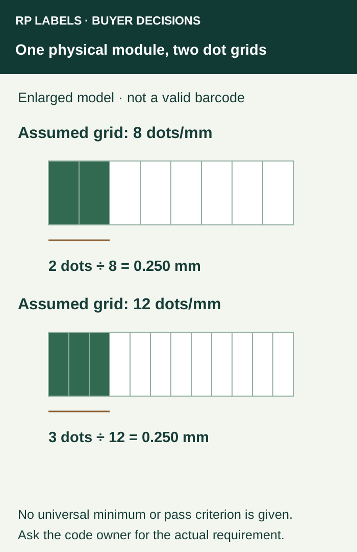
For a hypothetical grid of 8 dots/mm, a two-dot module is 2 ÷ 8 = 0.250 mm. On a hypothetical 12-dot/mm grid, three dots produce the same 0.250 mm. Keeping two dots on that second grid instead produces about 0.167 mm. The physical requirement has changed even though the template still says “2.”
These values demonstrate arithmetic. They are not recommended minimums, an RP resolution specification or acceptance limits for a GS1 symbol. The code owner must supply the applicable symbology, data, dimension range, quiet areas and any trading-partner requirements. If a requested dimension lies between device steps, return the possible whole-dot options for review rather than silently rounding and approving the result.
A printer change can shrink the whole layout
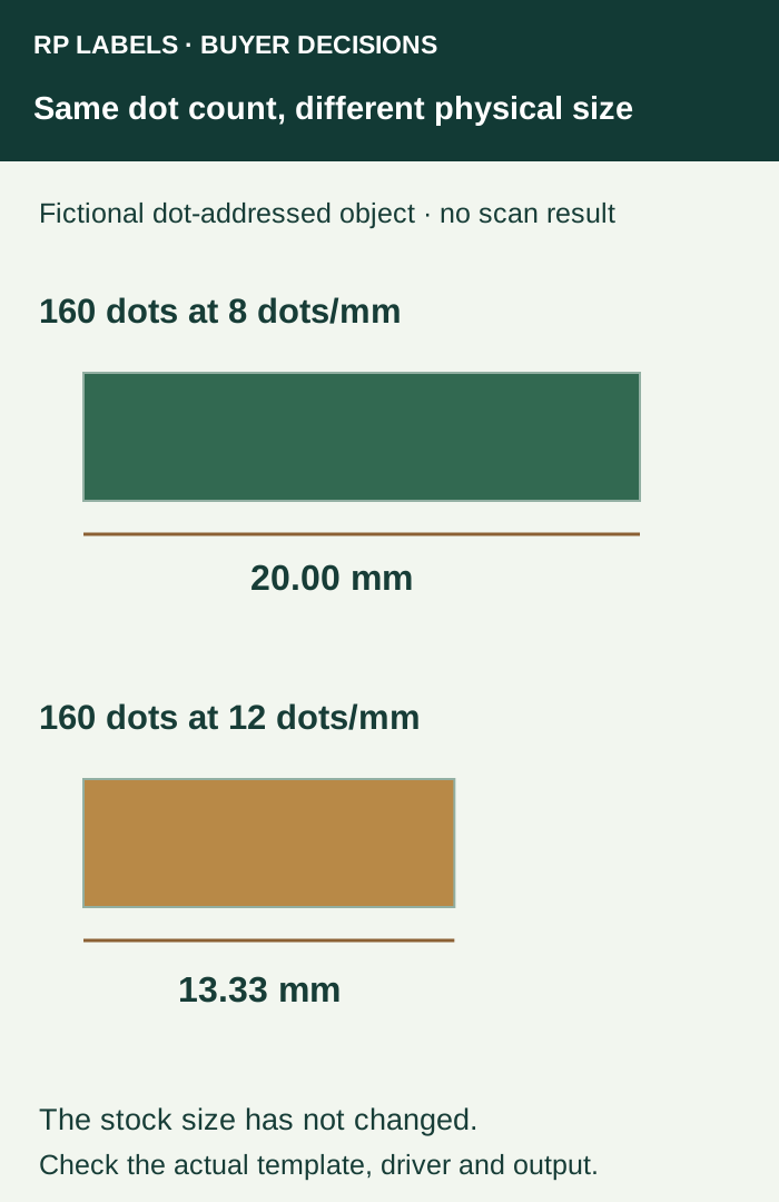
In the illustrated example, an object 160 dots wide occupies 20 mm at 8 dots/mm. Sent unchanged as 160 device dots at 12 dots/mm, it occupies about 13.33 mm. The label itself has not become smaller. Its printed field has. This model applies to an unchanged dot-addressed object; it does not diagnose every PDF printing problem.
An individual public packing-station discussion describes smaller output after a printer replacement. It is a useful question to investigate, not an RP customer case or proof of a universal cause. The print owner should also inspect page sizing, driver selection, application configuration and scaling. Do not copy a percentage from a forum comment into a barcode template.
Compare the output before buying replacement stock
| Observed change | First evidence to request | Keep separate |
|---|---|---|
| All printed objects changed size | Actual-size measurement, output file, driver and installed head reference | A new roll size is not automatically the remedy |
| Layout size is right, code elements differ | Symbol generation settings and physical module or narrow-element measurement | A successful beep is not formal print-quality verification |
| Flat code is readable, applied vial is difficult | Matched applied sample with the intended reader | Curvature and glare are distinct from device-grid selection |
Retain the approved encoded content and template revision. Print through the actual production route, measure the intended label and field, and compare decoded output with the authorized data. Where formal quality evidence is required, agree its scope with the responsible party; the verification guide explains that handoff. Inspect the applied vial separately using the curvature and orientation comparison.
Pause release if the output is unexpectedly scaled, required dimensions remain unresolved or the sample belongs to another head or template. If the current printer cannot supply a defensible footprint, discuss a larger field, another appropriate carrier or another qualified print route with the code and packaging owners. A higher-resolution machine is not an automatic requirement, and shrinking the barcode is not a universal solution.
Send the printer information with the label brief
For custom vial labels, send RP the actual vial, finished label size, quantity per design, artwork and the reserved later-print field. Include the exact local printer/head reference, confirmed physical symbol requirements and output-template revision. Prepare an inquiry asking which stock, window and sample scope can be quoted. Keep local template configuration and code acceptance with their named owners.